The Bamford "Hi-Ram Pump ®"
New Applications
[Introduction] [Latest News] [About the Pump] [Questions & Answers] [Prices]
[Pump Installation] [File Downloads] [New Applications] [Links] [Contact Us]
New Uses and Applications
Pump Operation
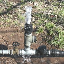
A picture of a basic Hi-Ram Pump pumping water and a diagram showing operation of the Waste Valve Mechanism are shown just below - for reference in the following discussion. The operation of the pump is also discussed in more detail in the section "About the Pump".
The new uses involve a rearrangement of the normal components of the pump, in some cases with additional components. The principle of operation of the waste valve assembly is not changed. However, the geometry of the components can be very important for successful operation, and the limits for operation are not yet clearly defined for these uses. You might therefore like to regard this page as the experimenter's section of the pump internet pages.
In all of these applications it must be remembered that the amount of power produced to do useful work is small, so that the benefits occur gradually over a period of time. This corresponds to the normal water pump role, where a small flow of water fills a tank over a period of time.
Pumping Air or Compressing Air
During each operating cycle of the Hi-Ram Pump the pressure in the pump body falls briefly below atmospheric pressure i.e. a vacuum is created. If the pump Non Return Valve is reversed and left exposed to the outside atmosphere, air will be sucked into the pump body to mix with the water inside the pump. This is the basis for the pump being able to pump air or generate compressed air.
Because the parts inside the waste valve stop water flow in both the upper and lower operating positions, the pump is much more efficient at generating a vacuum than other waste valve mechanisms that only seal in the upper position.
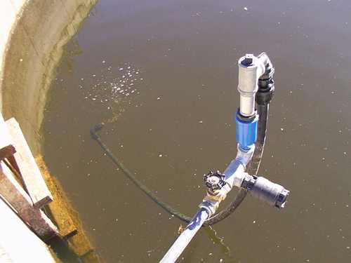
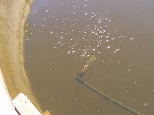
The pictures below show a test set up with a 25 mm in-line pump. Air is sucked in the black non-return valve on the right, and goes with the "waste" water down the 25 mm inch poly pipe to come out about 500 mm below the water surface. The pump is also about 500 mm above the water surface. In addition to air being pumped into the water below, the flow of waste water provides a circulation effect. This test was to demonstrate possibilities for a self powered pump to both aerate and destratify a pond, being things of interest to those engaged in aquaculture such as fish farming.
The extra in-line fittings on the top of the pump are not needed where the pump is being used simply to evacuate air. The normal fitting at the top of the pump is used, and the air taken into the pump comes out with the waste water.
To generate compressed air, the pump uses two non return valves (not shown in illustrations here). One non return valve is used to draw air into the pump body. The second valve performs the same role as in a normal water pump, except that a mixture of water and air is pumped into the delivery pipe. The geometry and operation of the pump for this use are most important, as it is necessary to separate the delivered air and water and also ensure that the pump does not fill up with air (which will stop it). Subject to a reduction in pump efficiency because of the air injection, air can be compressed up to the maximum outlet pressure capability of the pump.
With the same pump arrangement where the non return valve is reversed, the vacuum effect in the pump can also be used to draw in water through a suction line. Water that is sucked in exits the pump with the waste water that is operating the pump. The suction head that can be attained depends on the pump installation, although brief testing suggests that suction lifts of several metres are possible.
Where there is a separate flow of water available to drive a pump, this opens the opportunity for the pump to act as a de-watering device or sump pump.
There are applications where it would be useful to siphon water over an embankment, for example over the wall of a storage dam or pond. These applications are not always successful, because of the difficulty of initially priming the siphon and then maintaining the siphon effect. A siphon that is used intermittently or at a low flow rate tends to accumulate air in the upper part of the siphon, causing it to eventually stop.
While we are not aware of anyone doing this (so far), and depending on the arrangement of the siphon, a Hi-Ram Pump set up as an ancillary suction pump might provide the means of maintaining the prime in a larger siphon pipe.
If the Non Return Valve shown in the diagram near the top of this page is removed or blocked off, the Waste Valve Mechanism will operate and generate the maximum internal pressures possible for the conditions of operation. (This should NOT be done for drive heads more than about 4 metres). In other words, all the input energy into the pump is dissipated through the resultant water hammer and the associated effects in the pump, the drive pipe and the overall installation.
The magnitude of the water hammer can be easily adjusted using the pump adjustment tubes and by varying the drive head. The Waste Valve Mechanism can therefore also be regarded as a way to generate water hammer for experimental purposes, or to test the resistance to water hammer of other appliances or items connected into the pipework.
In the description concerning the pumping of air (above), the Hi-Ram Pump has extra fittings so that it operates as an in-line pump. An in-line arrangement can also be used in a normal water pumping role. This allows the waste water to be piped away in a closed system for other uses, instead of simply overflowing from the top of the pump.
The concept of an in-line pump also leads to the thought of whether the pipe for the waste water could be used to increase the effective drive head of the pump. Even if this is so, whether it is workable in a real installation is still another matter.
As a Power Source for Other Devices
As referred to above, the Waste Valve Mechanism will work on its own at the end of a drive pipe, generating high pressure pulses about once a second from the water hammer involved.
One way for the Hi-Ram Pump to act as a power source is to use these pressure pulses to operate other devices. For example, the pressure pulses could operate a diaphragm pump, which could be used to pump from another source of water. This would open the way to operate the Hi-Ram Pump on "dirty" water and pump "clean" water with the associated diaphragm pump.
As indicated before, although the amount of power available to do useful work is small, it can be useful when operation extends over a period of time.
![]()
Bamfords, Post Office Box 11, YASS NSW 2582, AUSTRALIA
Phone +(61 2) 6226 4068
Bamford Industries NSW BN97702171, and John Bamford and Associates NSW L8632225
"Hi-Ram Pump" is a Registered Trade Mark
Copyright ©Bamford Industries 1999-2014
Home Page http://www.bamford.com.au